

My Experience Unbricking a Netgear R6300V2 Router
This March, tempted by Zhang Dama, I finally caved and bought the legendary “electric stove”—the Netgear R6300V2 router—beginning my router-tinkering journey. At first, I just wanted to buy a router that could run OpenWRT firmware, then run Shadowsocks on it to achieve automatic network proxying. In fact, there are too many routers that meet this need; a router costing around 100 yuan could do the job. But the longer I browsed on Zhang Dama, the more uneasy I felt, thinking that maybe I should go all-in at once: just buy a dual-band router with stronger performance, one that could also mount a portable hard drive and serve as a mini NAS. Just imagining it felt wonderful. So, the R6300V2 became the obvious choice.
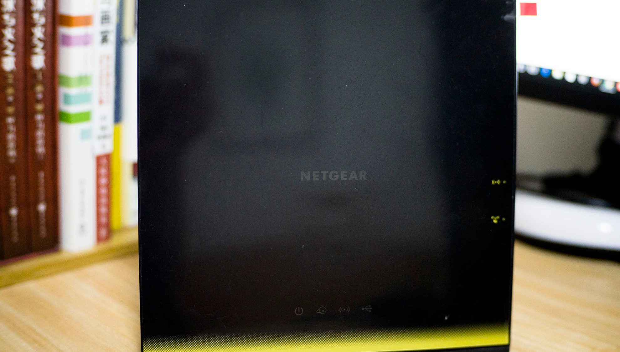
This March, tempted by Smzdm (Zhang Dama), I finally caved and bought the legendary 'electromagnetic stove'—the Netgear R6300V2 router—and started my router-tinkering journey. At first, my idea was simply to buy a router that could be flashed with OpenWRT firmware, then run Shadowsocks on it to achieve automatic proxying of network traffic. In fact, there are far too many routers that satisfy this requirement; one costing about 100 yuan can do the job. But the longer I browsed Smzdm, the more uneasy I felt, thinking that maybe I should get it right in one step: just buy a dual-band model with stronger performance, that can also mount a portable hard drive and serve as a mini NAS. Just imagining it felt wonderful. And so, the R6300V2 became the one and only choice.
Since buying it until now, I have flashed several firmware images one after another: first the Merlin firmware from koolshare.cn, then DD-WRT, then Tomato. However, when flashing Tomato, I forgot to restore the factory settings, which bricked the router after the flash. After connecting my computer to it, the computer could not be assigned an IP address, and I could not ping 192.168.1.1, so this led to my unbricking experience. I searched online and found that the R6300V2 could be rescued by connecting it to a computer with TTL wires and then reflashing the system in TFTP flashing mode, so I immediately bought a serial flashing module from Taobao (Jack Ma's place) and prepared to start flashing.
The serial module arrived quickly, and that night I studied online tutorials all night before starting to tinker. Fortunately, I had just been thinking that my mirrorless camera had not been used in a long time, so I figured I might as well use it to document the whole tinkering process. That night, I disassembled the router while taking photos, and sometimes I even had to think carefully about how to make the shots look better. I have to say, this experience was indeed quite fun, and it really brought many benefits to my later blog writing. On the one hand, I had image material for articles; on the other hand, I could practice my photography skills and keep my camera from gathering dust—truly a win-win. It just felt like the whole process was a bit time-consuming, uh. OK, enough rambling; below I will start describing the entire process.
Disassembly
The R6300V2 is very easy to disassemble; you only need to unscrew the three screws on its underside. The picture below is its bottom view:
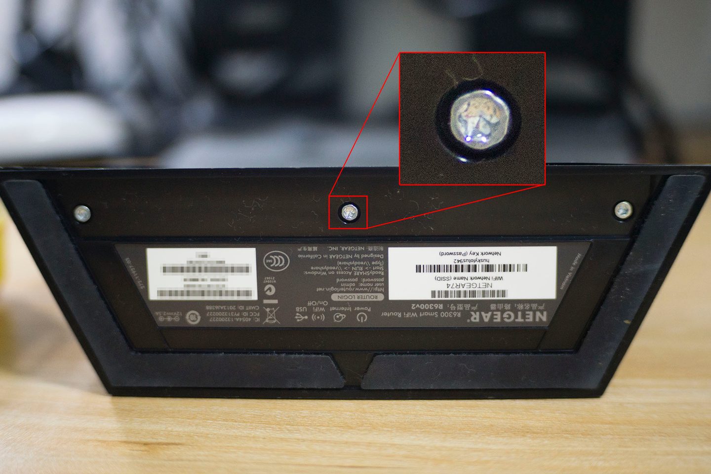
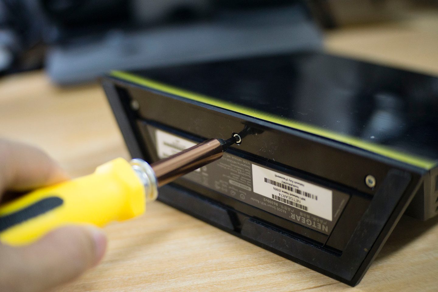
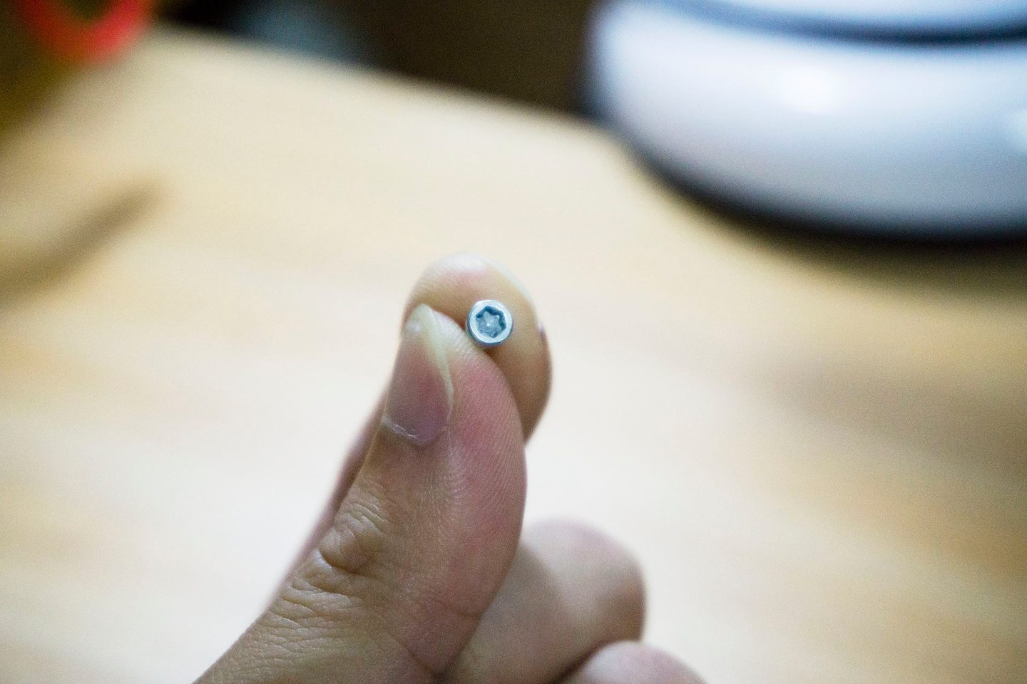
After all the screws are removed, you need to use a knife to pry open the router's outer shell. ==First, gently pry open a gap along the bottom edge of the router's front panel, then gently pry along the left and right sides of the router, so that the outer shell can be lifted off easily.== Once it is lifted off, you can remove the front panel as a whole piece, and then you can see the router's core circuit board.
Pry open the lower panel and the left and right sides After prying it open, you can lift off this panel. Once the panel is removed, you can see the router's circuit board.
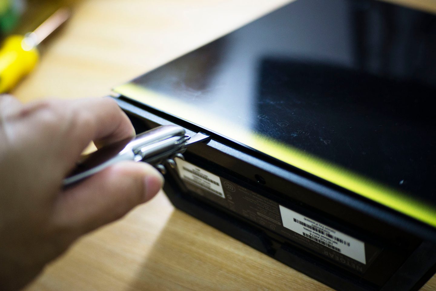
Pry open the lower panel
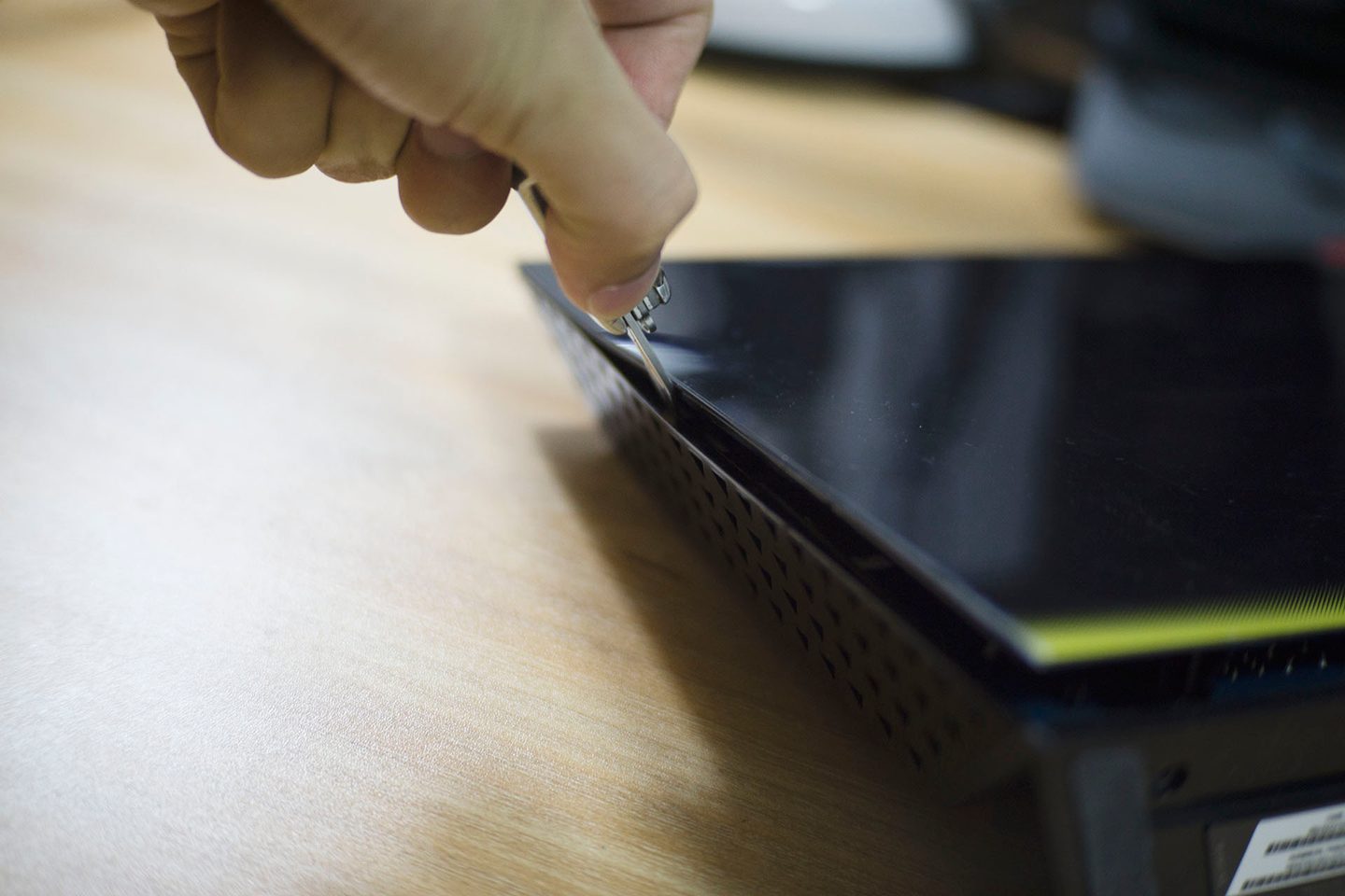
and the left and right sides
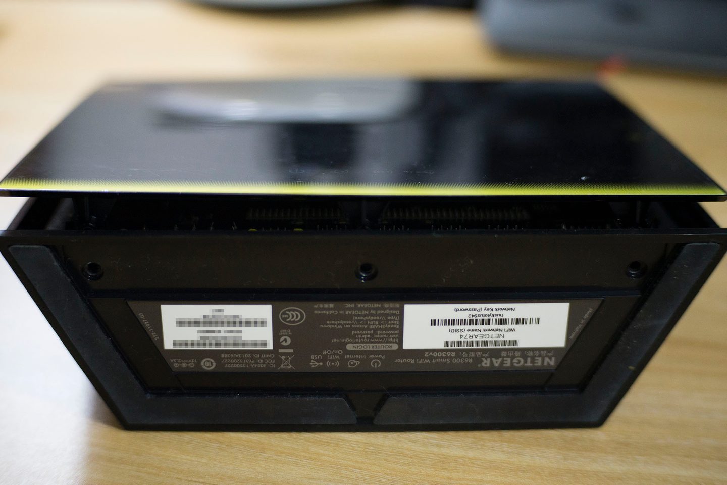
After prying it open, you can lift off this panel.
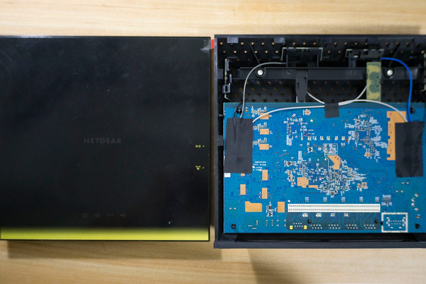
Once the panel is removed, you can see the router's circuit board.
Because the R6300V2's TTL pins are on the front side of the circuit board, disassembly is not yet complete at this step; you need to continue taking it apart and remove the entire circuit board. As can be seen from the image above, to remove the entire circuit board, you also need to unscrew two screws, then bend the router slightly outward so that the circuit board is not held in place by the plastic shell.
There is a trick here: after removing the screws, pry the outer shell outward, then push the Ethernet jack on the back of the circuit board firmly with your fingers; this makes it easier to push the circuit board out.
The two red circles above are the screws that need to be unscrewed, and the red circle below is the plastic that holds the circuit board in place and prevents it from coming out.
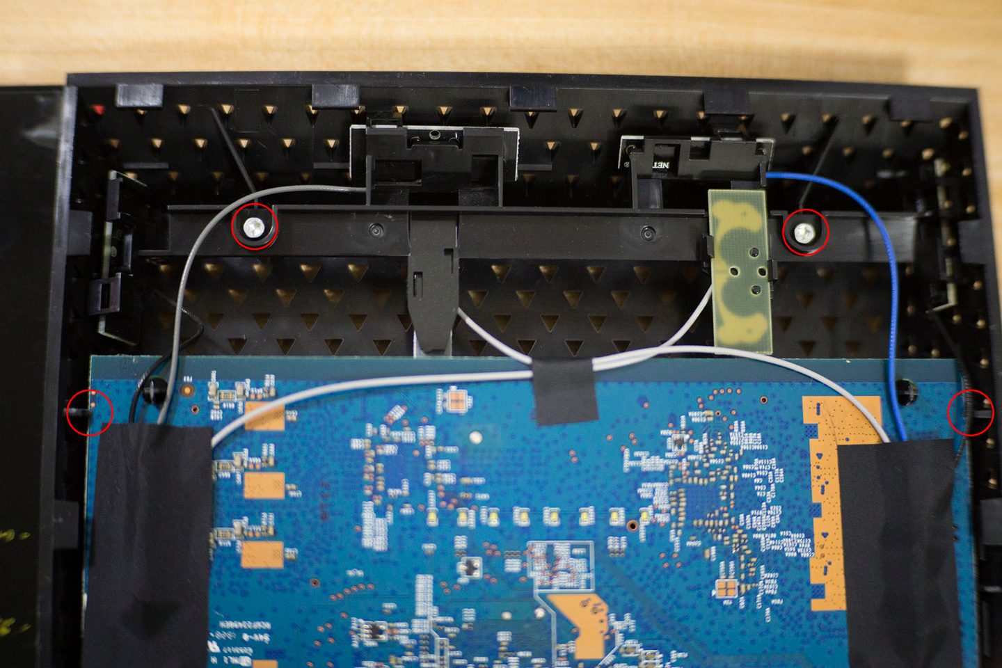
The two red circles above are the screws that need to be unscrewed, and the red circle below is the plastic that holds the circuit board in place and prevents it from coming out.
After the circuit board is removed, you can see its front side, which looks like this:
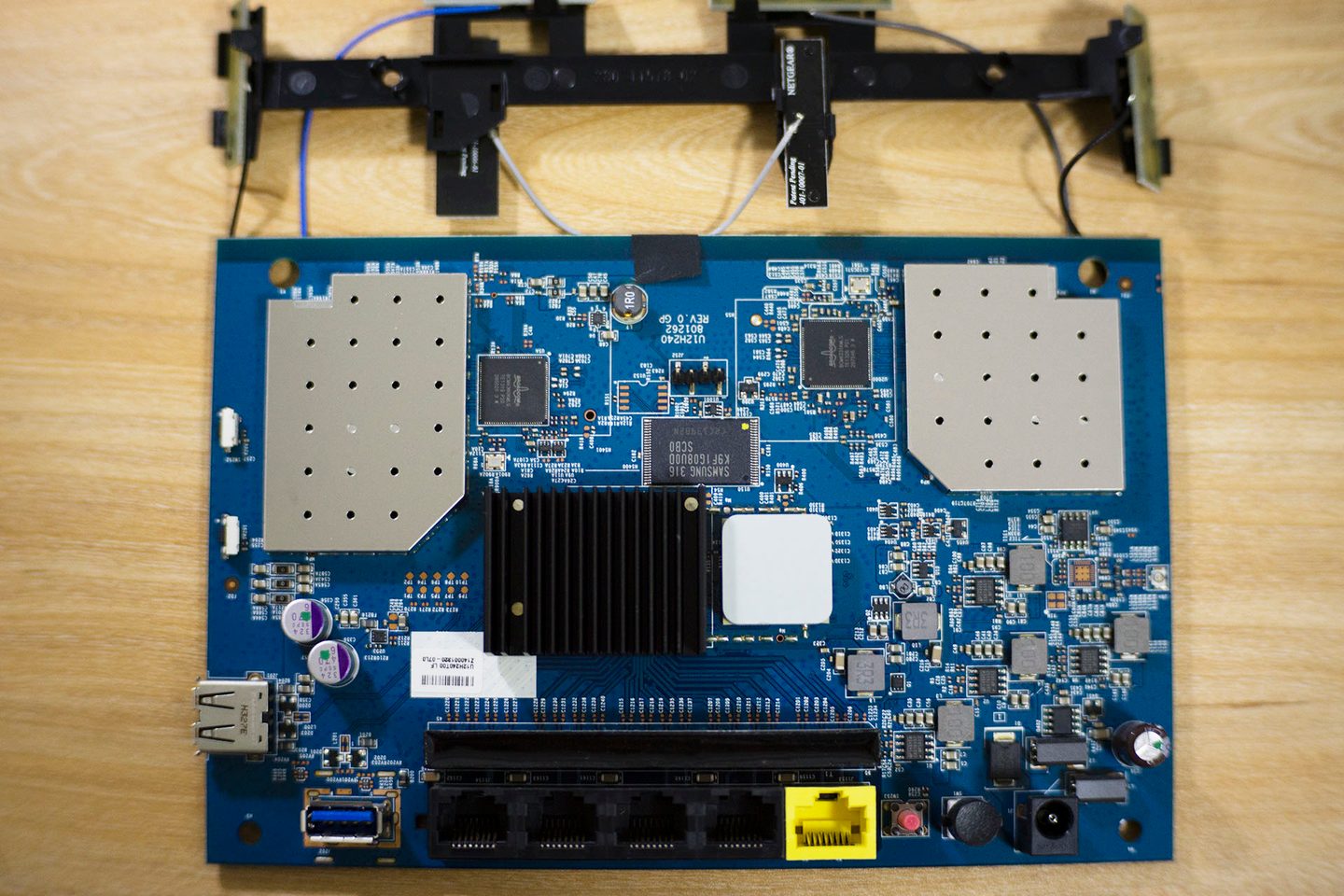
All the chips are clearly visible. At this point, you can find our TTL pins, located in the J252 area. The TTL pins consist of 4 pins; from left to right, the definitions of these four pins are as follows:
VCC 、G、T、R . These four pins are the ones that need to be connected to the flashing cable, and the order is very important. This will be explained next.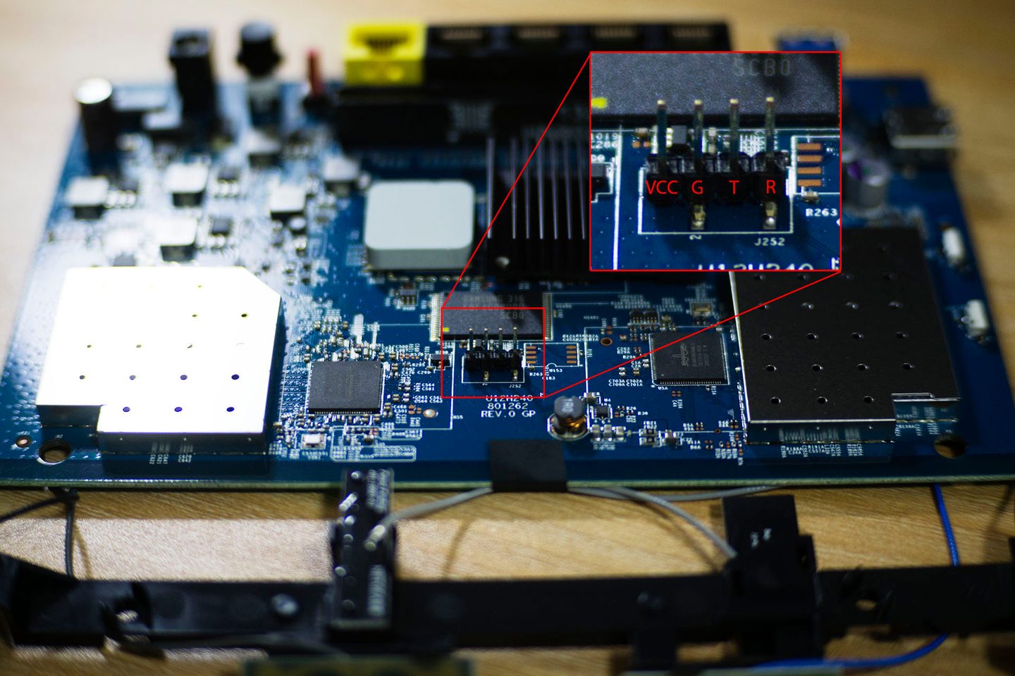
Connect to the computer using the flashing cable
R6300V2 requires a flashing cable to connect to the computer, so on the all-powerful Taobao I boughtthis serial port module, and it seems pretty good. This serial port module is a gold-colored thing similar to a USB flash drive, and the seller also gave several flashing cables; each flashing cable is a different color, which makes it easier for us to tell whether each cable is connected correctly. The serial port module itself also has several pins, namely
GMD、RXD、TXD、3V3、5V, of which, during the entire unbricking process only GMD 、RXD、TXD these three pins were used.Never connect the `3V3` or `5V` pins to the router, i.e., do not connect powered pins to the router, as it may damage the router!
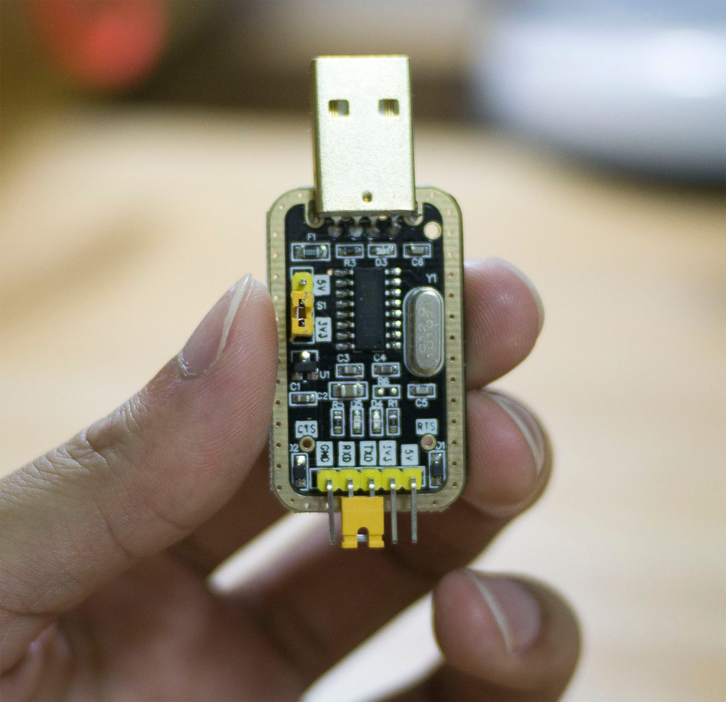
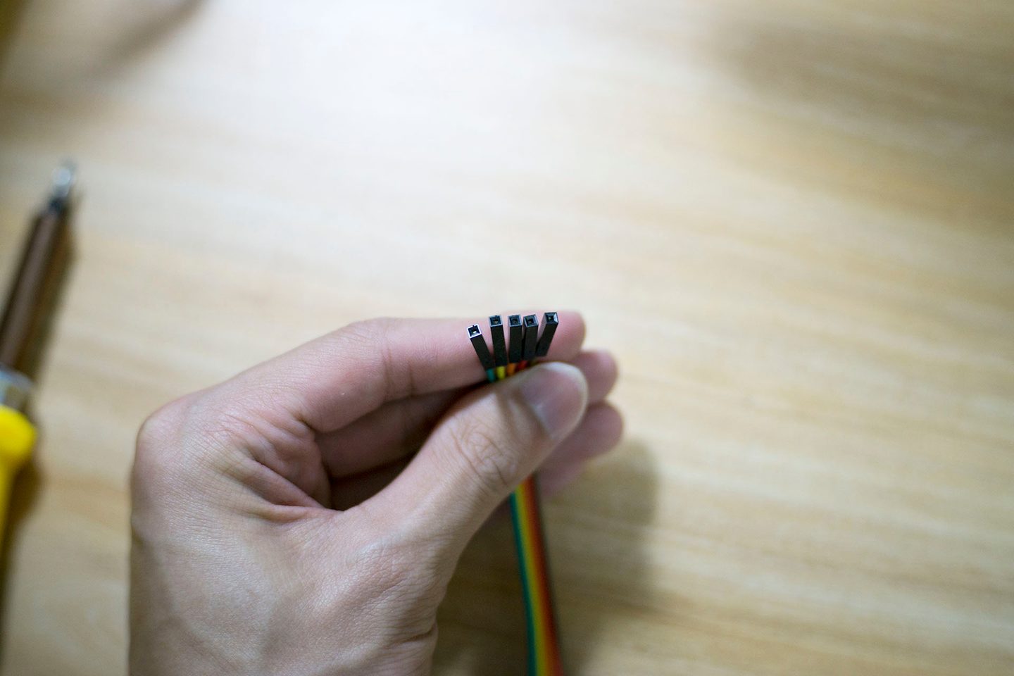
Next, connect the serial port module to the router using the flashing cable. The connection order is:
- the router's
Gpin connects to the serial port module'sGMDpin - the router's
Tpin connects to the serial port module'sRXDpin - the router's
Rpin connects to the serial port module'sTXDpin
Simply put
G-G ,T-R ,R-T . As shown in the figure below, you can judge whether the connection is correct by observing the colors of the flashing cables connected at both ends.On the flashing cable connected to the router, the brown wire is connected to the G pin, the red wire is connected to the T pin, and the orange wire is connected to the R pin
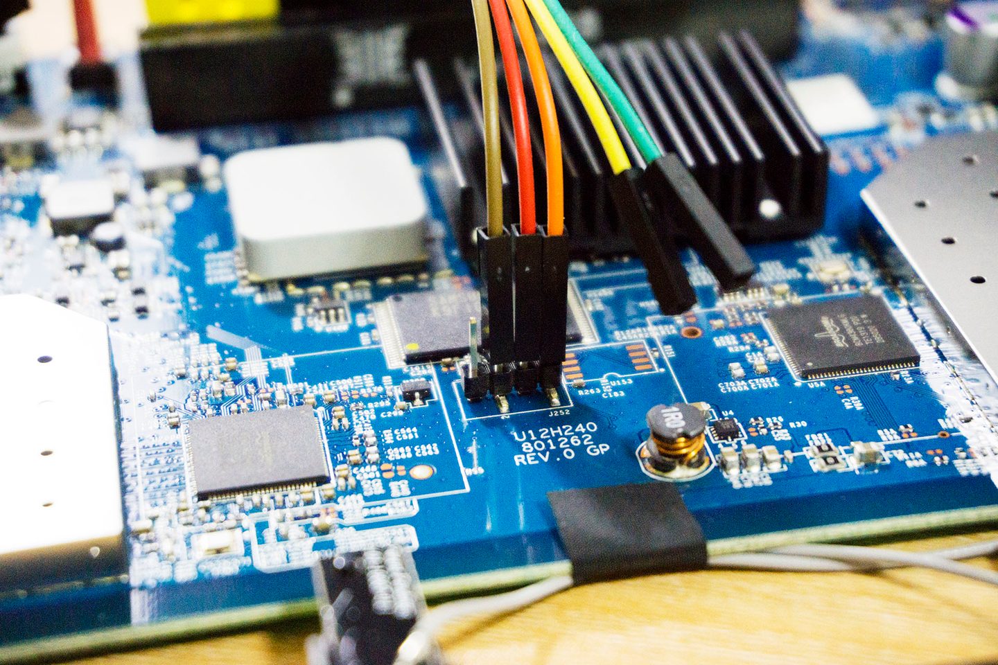
On the flashing cable connected to the router, the brown wire is connected to the G pin, the red wire is connected to the T pin, and the orange wire is connected to the R pin
On the flashing cable connected to the serial module, the brown wire is connected to the GMD pin, the red wire is connected to the RXD pin, and the orange-yellow wire is connected to the TXD pin
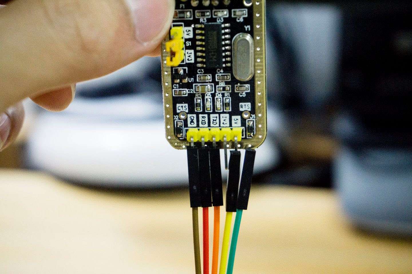
On the flashing cable connected to the serial module, the brown wire is connected to the GMD pin, the red wire is connected to the RXD pin, and the orange-yellow wire is connected to the TXD pin
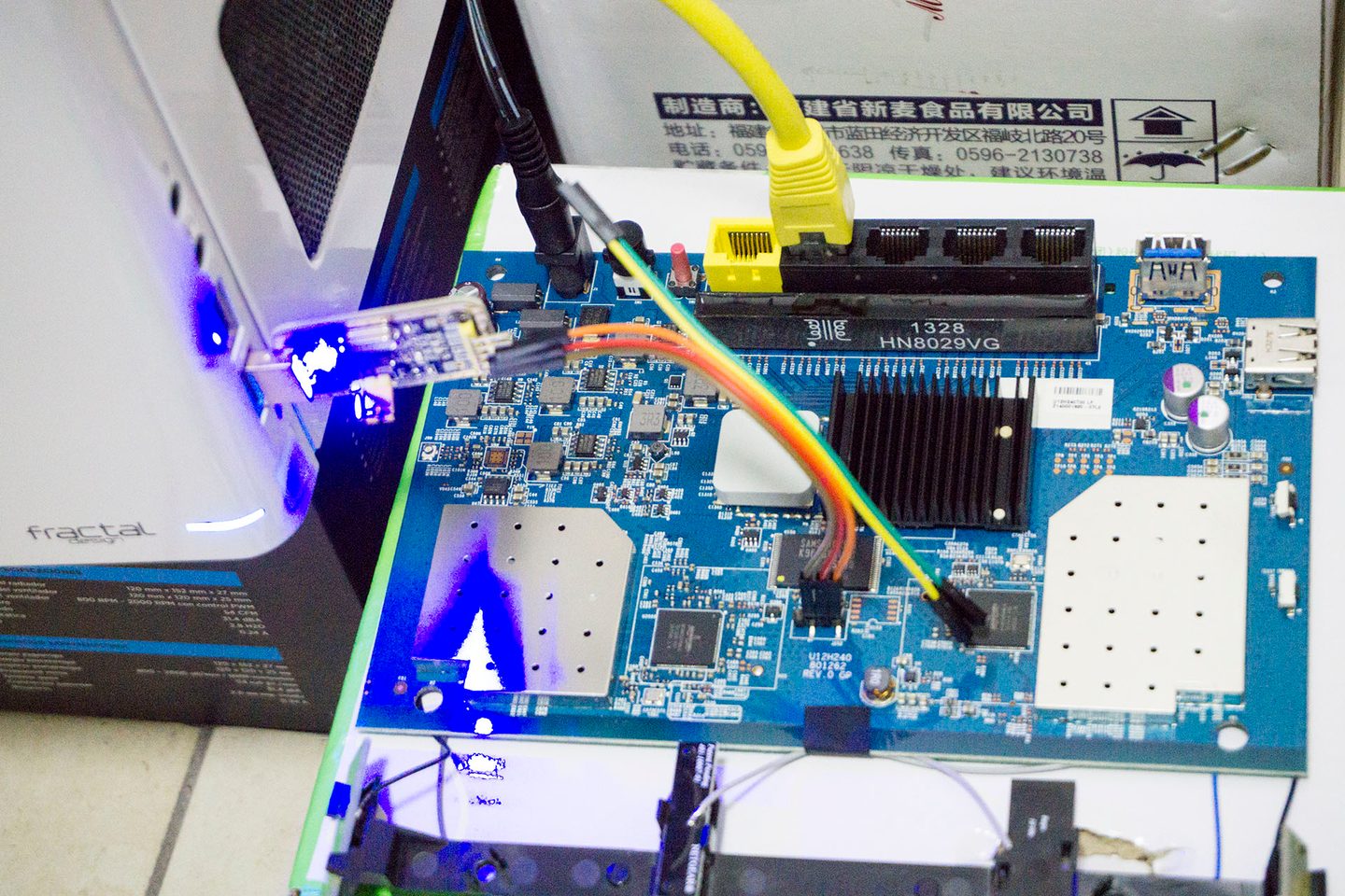
After confirming that the flashing cable connections are correct, you can plug the serial module into the computer's USB port.
Flash the recovery system
When using the serial module for the first time, you need to install the driver first. The Taobao page of the module I bought has the driver download; after downloading it, run the installer. Then plug in the serial module, and you can see the serial module in the computer's Device Manager. On my computer, it is on COM3, but this is not fixed and will change depending on which USB port you plug it into.
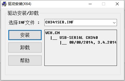
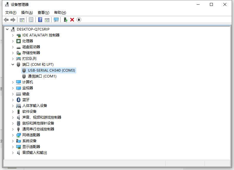
In addition to installing the driver, you also need to install a PuTTY software to connect to the serial module. After successful installation, run the program, then set the connection information, and select the
Serial , enter the corresponding COM port and baud rate. The baud rate of the R6300V2 is 115200, so enter 115200 here. After filling it in, click Session in the left sidebar, in Connection type inside, select Serial , at this point the connection information we just set will be displayed.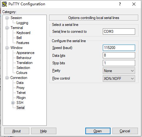
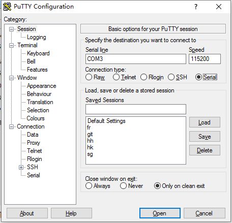
After the settings are complete, you can click
Open Open the connection. Note that if the serial module is not plugged into the computer at this point, or if the COM port you entered is incorrect, the connection will fail right away and show that it cannot connect to the serial port. In that case, you need to check which port you plugged into and whether you entered the wrong serial port.Generally, before connecting the router to the serial module, you can first connect the serial module to the computer, then use the PuTTY program to connect to the serial module. At this point, because the router is not connected to the serial module, the PuTTY display will be completely black with nothing shown, but it will not report an error. This state indicates that PuTTY has connected successfully and is waiting for data to be transmitted from the serial module to the computer. Only then do you need to use the flashing cable to connect the router and the serial module.
The next step is the most important and the most error-prone. When I was messing around with it, because I did not know the correct way to enter the router's TFTP mode, I spent a long time struggling; PuTTY showed no activity at all, so I thought my router was completely dead and could not even enter TFTP. After many attempts, I finally discovered that my method of entering TFTP was wrong. The correct steps are as follows:
- As described above, first connect the serial module and open PuTTY, putting PuTTY into the waiting state.
- Power off the router, then first use an Ethernet cable to connect the router to the computer, and configure a static IP on the computer as 192.168.1.2.
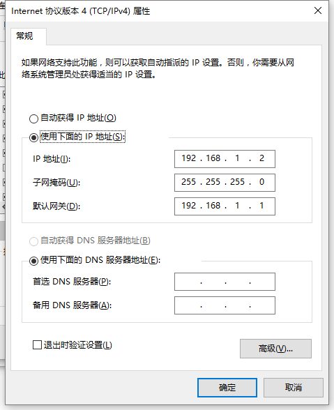
- Power on the router, and quickly use the flashing cable to connect the router and the serial module.
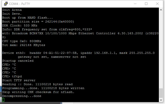
- If all goes well, you should see text continuously scrolling in PuTTY at this point, as shown in the figure below. At this time, you need to keep pressing Ctrl + C on the keyboard to terminate the router's boot process and enter TFTP mode.
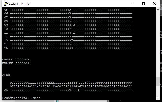
- If all goes well, the router will eventually enter TFTP mode at this point, and you can then enter
tftpdand press Enter to start the TFTP service on the router. As shown:
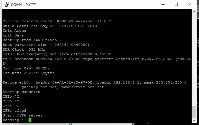
- At this point, you can ping the router:
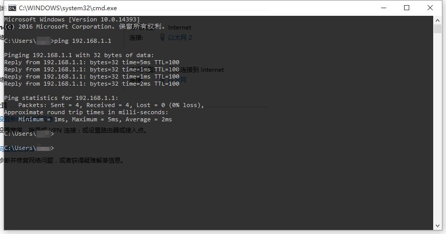
- Start the TFTP client of the Windows system:Open Control Panel -> Open Programs and Features -> On the left, click
打开或关闭 Windows 功能-> Check TFTP Client - Download the R6300V2 recovery firmware R6300v2-V1.0.0.16_1.0.8PRRU.chk to your computer's desktop.
- Start the CMD terminal, go to the desktop directory, and run
tftp -i 192.168.1.1 put R6300v2_V1.0.0.8_1.0.4PRRU.chk, wait a moment, and the transfer will succeed.
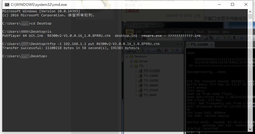
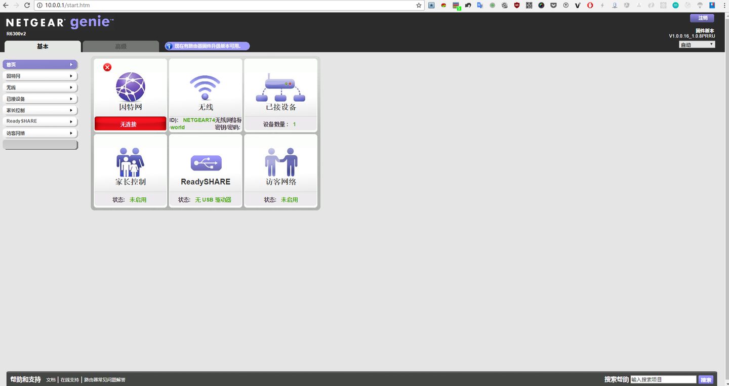
- After the transfer succeeds, PuTTY will start showing activity. The router will first unpack the firmware, then enter the flashing process, and after successful flashing it will begin rebooting the router. After a few minutes, you can access it via the web page http://192.168.1.1 to enter the router's settings interface. You will see the familiar NETGEAR router control interface. At this point, the entire brick-recovery process is complete, and you can start tinkering with the router again.
Reassembly
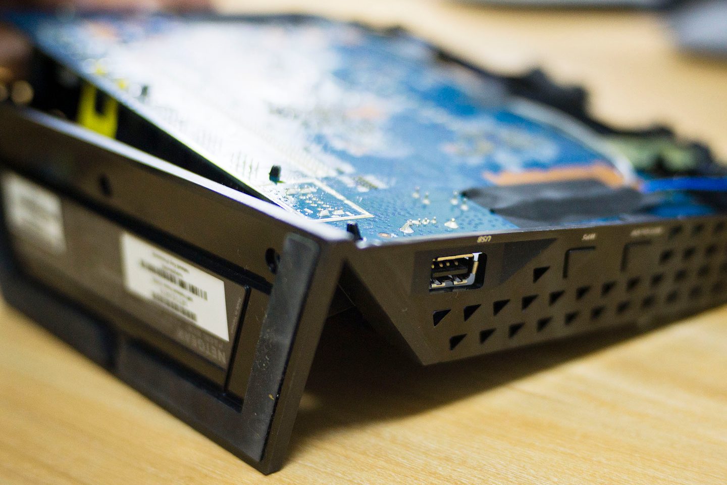
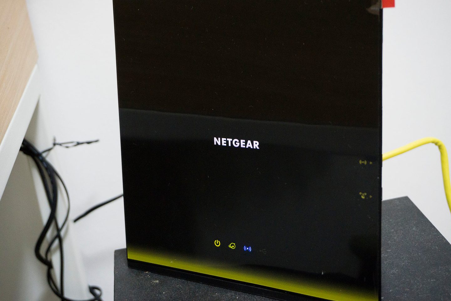
After the router has been successfully unbricked, you need to put the router's circuit board back into the plastic housing. The process of putting it back is also very simple; just note that when installing the circuit board back, first install the right side with the USB port, then install the other side, which makes it easier to put back. After the circuit board is put back, only tightening the screws remains; I won't repeat that. Below are photos of the circuit board being put back, as well as nice photos after it is assembled and powered on.
Some thoughts
I have to say the whole unbricking process was quite interesting, although I ran into problems when using PuTTY to connect to the computer. At first, I always connected to the serial module only after the router had finished booting, which left PuTTY completely black with no response at all. Later, I also wondered whether the flashing cable was connected incorrectly, so I unplugged and reconnected it again and again; if one order didn't work, I tried the reverse, but the result was the same—no response. Fortunately, in the end, after repeatedly hitting dead ends, I accidentally succeeded in testing it, and content finally appeared in PuTTY. But unfortunately I was too late to interrupt the router's boot, so I couldn't enter TFTP mode. However, I could enter the router's sh, but since I still couldn't send files to the router, it still didn't work. After two or three more attempts, I finally figured out the correct steps to enter TFTP: power off and disconnect the serial module, then power on, quickly connect the serial cable, and quickly press in PuTTY
Ctrl + C to enter TFTP.The whole unbricking process took roughly one night. But actually, I had already explored the R6300V2 disassembly process a few nights earlier, so I had a general understanding of how to disassemble the R6300V2. It was then that I decided to use my mirrorless camera to record the subsequent unbricking process. After all, I found it to be a very interesting process, and I rarely had such an opportunity to disassemble an electronic product and perform some recovery operations. As it turned out, the whole process was not difficult; as long as you are a bit careful, you can easily get it done. If you are practiced at tinkering, the entire disassembly and unbricking process should take less than an hour.
This experience more or less reminded me of my college days, since, after all, my college major wasCommunication Engineering, all day long I dealt with analog and digital electronics, as well as various circuit boards. However, since I wasn't interested in those things at the time, I devoted more energy to Web front-end development, which led to much of the specialized knowledge being learned only to get by; I only frantically crammed right before the end of term to get through the final exams. As a result, I now have no memory at all of the specialized knowledge from my university years. I forgot everything. This makes me feel somewhat ashamed now. After all, hands-on tinkering with electronic products is actually quite fun.
However, I don't regret what I did back then. Every choice has its pros and cons. If the me of those years had chosen to seriously study specialized knowledge, then I would inevitably have had no time to learn Web front-end knowledge, and there would be no current me writing an article like this. Perhaps that version of me would have been a qualified engineer in the telecommunications industry, but definitely not like the current me. (Talking nonsense with a straight face😀)